
This guided exercise covers the SDN module of our five-day Proxmox VE training. The full program covers VLAN zones, VXLAN overlays, EVPN with BGP, and the integrated firewall.
Guided Exercise: VXLAN Overlay with Proxmox VE 9 SDN
Create a VXLAN overlay network on your Proxmox VE cluster using Software Defined Networking. When you finish this exercise, two VMs on different physical nodes will communicate over an isolated L2 segment that survives live migration without any network reconfiguration.
Outcomes
At the end of this exercise, you will be able to:
- Create an SDN Zone of type VXLAN with peer addresses for tunnel endpoints.
- Create a VNet and a Subnet inside that zone.
- Apply the SDN configuration cluster-wide and verify the VXLAN interfaces on each node.
- Attach a VM to the VXLAN overlay and test L2 connectivity across nodes.
- Confirm that VXLAN connectivity survives live migration.
Prerequisites
- A three-node Proxmox VE 9.2 cluster (cluster setup guide).
- Shared storage (Ceph or NFS) for live migration testing (Ceph deployment guide).
- An underlay network connecting all three nodes. This can be the Corosync network, a dedicated VLAN, or any routed subnet. The VXLAN tunnels run on top of this network. For this exercise, the underlay uses 10.20.22.0/24 (the same VLAN used for the cluster network).
- At least one running VM (or a Cloud-Init template to clone from) to test the overlay network.
Addressing for this exercise:
| Node | Underlay IP (tunnel endpoint) |
|---|---|
| pve-node1 | 10.20.22.21 |
| pve-node2 | 10.20.22.22 |
| pve-node3 | 10.20.22.23 |
The overlay network will be 10.200.0.0/24 with VNI 5000. Replace all addresses with your own.
Instructions
1. Create the VXLAN zone
An SDN zone defines the type of virtual network and the underlay transport. A VXLAN zone needs the list of all tunnel endpoints (peer addresses) so each node knows where to send encapsulated frames.
1.1. Open the SDN configuration in the web UI.
Navigate to Datacenter → SDN → Zones, then click Add and select VXLAN.
1.2. Configure the zone.
| Field | Value | Purpose |
|---|---|---|
| ID | vxlanzone | Zone name (lowercase, no spaces) |
| Peer Address List | 10.20.22.21,10.20.22.22,10.20.22.23 | Underlay IPs of all three nodes |
| MTU | auto | Proxmox calculates 1450 (1500 minus 50 bytes VXLAN overhead) |
Important: The peer addresses must be the underlay (transport) IPs, not the management IPs. These addresses are the tunnel endpoints where VXLAN frames are encapsulated and decapsulated. Using management IPs instead of the dedicated transport network works but mixes overlay traffic with management traffic.
Click Add to create the zone.
2. Create the VNet
A VNet is a virtual network inside a zone. It maps to a Linux bridge on each node and carries traffic tagged with a VXLAN Network Identifier (VNI).
2.1. Navigate to VNets.
In Datacenter → SDN → VNets, click Create.
2.2. Configure the VNet.
| Field | Value |
|---|---|
| Name | vnet5000 |
| Zone | vxlanzone |
| Tag | 5000 |
The tag is the VNI. VXLAN supports up to 16 million VNIs (24-bit identifier), far beyond the 4 094 limit of traditional VLANs. Leave Isolate Ports and VLAN Aware unchecked for this exercise.
Click Create.
3. Create the Subnet
3.1. Add a subnet to the VNet.
Select the VNet vnet5000, open the Subnets tab, and click Create.
| Field | Value |
|---|---|
| Subnet | 10.200.0.0/24 |
| Gateway | (leave empty) |
| SNAT | unchecked |
This subnet is a pure L2 overlay segment with no routing and no NAT. VMs attached to it communicate at layer 2 only. If you need the overlay to reach external networks, add a gateway and enable SNAT.
4. Apply the SDN configuration
SDN changes in Proxmox are staged: they exist in the configuration but are not active on the nodes until you explicitly apply them.
4.1. Click Apply in the SDN panel.
In Datacenter → SDN, click the Apply button at the top. Proxmox pushes the configuration to all cluster nodes simultaneously. The zone status changes from new to available.
4.2. Verify the VXLAN interface was created on each node.
SSH into any node and check:
root@pve-node1:~# ip -d link show type vxlan
You should see an interface named vxlan_vnet5000 with VNI 5000 and a destination port of 4789 (the standard VXLAN UDP port). The interface has an MTU of 1450.
Repeat on nodes 2 and 3. All three nodes must have the interface.
4.3. Verify the bridge.
root@pve-node1:~# ip link show vnet5000
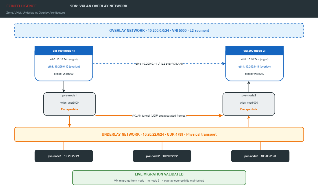
The VNet appears as a Linux bridge named vnet5000. The VXLAN interface is enslaved to this bridge. When a VM is attached to vnet5000, its virtual NIC connects to this bridge, and traffic is encapsulated into VXLAN frames and sent to the peer nodes via the underlay.
5. Attach VMs to the overlay
You need two VMs to test connectivity. This exercise assumes you have a running VM or a Cloud-Init template. Adjust the VM IDs and IPs to your environment.
5.1. Add a second NIC to VM 100 on node 1.
In the web UI, select VM 100 → Hardware → Add → Network Device:
- Bridge:
vnet5000(the SDN VNet appears in the dropdown alongside regular bridges) - Model: VirtIO
- Firewall: checked
Inside the VM, configure the new interface with a static IP:
$ sudo ip addr add 10.200.0.10/24 dev eth1
$ sudo ip link set eth1 up
For a persistent configuration, add the IP to /etc/netplan/ or /etc/network/interfaces depending on your guest OS. If you use Cloud-Init, set ipconfig1 to ip=10.200.0.10/24.
5.2. Add a second NIC to VM 200 on node 2.
Repeat the same procedure: add a NIC on bridge vnet5000, then configure the IP:
$ sudo ip addr add 10.200.0.11/24 dev eth1
$ sudo ip link set eth1 up
5.3. Test L2 connectivity across nodes.
From VM 100 (node 1), ping VM 200 (node 2) via the overlay:
$ ping -c 3 10.200.0.11
PING 10.200.0.11 (10.200.0.11) 56(84) bytes of data.
64 bytes from 10.200.0.11: icmp_seq=1 ttl=64 time=1.25 ms
64 bytes from 10.200.0.11: icmp_seq=2 ttl=64 time=0.45 ms
64 bytes from 10.200.0.11: icmp_seq=3 ttl=64 time=0.48 ms
Zero packet loss confirms the VXLAN tunnel is working. The two VMs are on different physical nodes but share the same L2 broadcast domain via the overlay.
What happens under the hood: when VM 100 sends an Ethernet frame to 10.200.0.11, the frame enters the vnet5000 bridge on node 1. The bridge forwards it to the vxlan_vnet5000 interface, which encapsulates the original Ethernet frame inside a UDP packet (destination port 4789) addressed to the underlay IP of node 2 (10.20.22.22). Node 2 receives the UDP packet, decapsulates the inner Ethernet frame, and delivers it to VM 200 via its local vnet5000 bridge. The VMs never see the encapsulation — they operate as if they were on the same physical switch.
6. Validate after live migration
The real test of an overlay network is whether it survives live migration. When a VM moves to a different physical node, the VXLAN tunnel endpoints change, but the VM’s overlay address must remain reachable.
6.1. Migrate VM 100 from node 1 to node 3.
root@pve-node1:~# qm migrate 100 pve-node3 --online
Wait for the migration to complete. The output shows the transfer duration and downtime (typically under 100 ms).
6.2. Test overlay connectivity again.
From VM 100 (now on node 3), ping VM 200 (still on node 2):
$ ping -c 3 10.200.0.11
The ping must succeed with zero packet loss. The overlay network reconfigured automatically: the VXLAN tunnel now runs between nodes 3 and 2 instead of nodes 1 and 2. No manual network changes were needed. This is the core value of SDN: the logical network is decoupled from the physical topology.
Validation checklist
| Criterion | Verification |
|---|---|
| Zone created and available | Web UI: Datacenter → SDN → Zones shows vxlanzone as available |
| VNet active on all nodes | ip link show vnet5000 on each node |
| VXLAN interface present | ip -d link show type vxlan shows VNI 5000 |
| L2 connectivity | Ping between VMs on overlay: 0% loss |
| Post-migration connectivity | Ping still works after qm migrate --online |
What Proxmox VE 9.2 adds to SDN
Proxmox VE 9.2 introduced two additions to the SDN stack worth noting for future use:
- WireGuard as a fabric protocol. You can now build encrypted site-to-site overlays between clusters using WireGuard tunnels as the underlay transport, replacing unencrypted VXLAN for inter-datacenter links.
- BGP/EVPN filtering. Route maps and prefix lists give fine-grained control over which routes are advertised between EVPN zones, enabling more complex multi-tenant and multi-site topologies.
These features build on top of the VXLAN foundation you deployed in this exercise.
What this article does not cover
This exercise creates a single VXLAN zone with one VNet. The following topics are addressed in separate articles or through our cloud and virtualization practice:
- Simple zones and VLAN zones for traditional network segmentation.
- EVPN zones with BGP for multi-site L3 routing over VXLAN.
- The Proxmox integrated IPAM for automatic IP assignment in SDN subnets.
- The Proxmox VE firewall applied at VNet level for overlay security policies.
- WireGuard fabric configuration for encrypted inter-datacenter overlays.
- Multiple VNets within a single zone for micro-segmentation.
Sources: Proxmox VE 9 Administration Guide, Software Defined Network chapter, pve.proxmox.com. Proxmox VE 9.2 release notes (Dynamic Load Balancer, SDN WireGuard, BGP/EVPN). EC INTELLIGENCE, Formation Administration Proxmox VE 9, Chapter 7, January 2026.